
Moving from simple but messy electronics to semi-industrial PCB solutions is neither easy nor quick when certification is the goal. And yet, we’re pretty much there now. Assembly and testing are next.
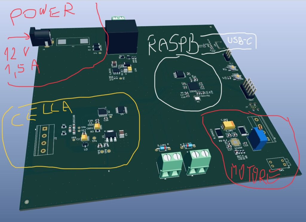
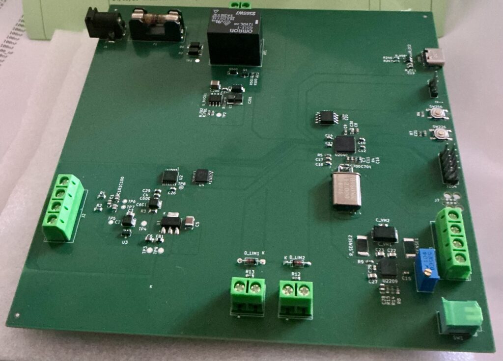
Preliminary summary — all electrical checks on the bare board passed:
• No shorts between +12V, +5V, +3V3_DIG, +3V3_ANA, VREF and GND/AGND
• Full continuity along all expected paths (regulator→ferrite bead, feedback divider, USB protection)
• No shorts on any pin of J206, including D+/D-
• No shorts on D_USB1
• Everything consistent with the schematic, no surprises.
EDIT (30 Jul): Discrepancies between KiCad’s default libraries and the datasheets for two key parts require a v1.1 revision. Although the PCB layout and physical geometry appear sound, this update also offers an opportunity to incorporate additional fail-safe measures. No copper damage was found.